|
|
|
ACCES I/O
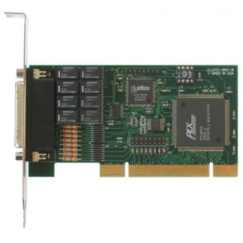
Low profile, eight isolated digital inputs and eight relay outputs card |
|
 INTERNATIONAL GROUND SHIPPING: INTERNATIONAL GROUND SHIPPING: For qualified orders, we will waive the Brokerage/Handling Fee for Custom Clearance and Documentation No other hidden fees will be collected from you when packages arrive. Guaranteed [ Detailed Explanation ] |
|
Product Description: FEATURES FUNCTIONAL DESCRIPTIONThe LPCI-IIRO-8 is a half-size Low-Profile PCI bus compatible card that provides isolated digital input and output interface for PCI-Bus computers. The card has eight optically-isolated digital inputs for AC or DC control signals and eight electromechanical relay outputs. LPCI-IIRO-8 occupies four consecutive 8-bit registers in I/O space.
InputsThe LPCI-IIRO-8 provides eight optically-isolated inputs. These inputs can accept either AC or DC signals and are not polarity sensitive. Input signals are rectified by photocoupler diodes while unused power gets dissipated thru a 1.8k-ohm resistor in series. The inputs may be driven by either DC sources of 3 to 31 volts (rms) or AC sources at frequencies of 40 Hz to 10 KHz. Standard 12/24 AC control transformer outputs can be accepted as well. External resistors connected in series may be used to extend the input voltage range, however this will raise the input threshold range. Consult with factory for available modified input ranges. Each input circuit contains a switchable filter that has a 4.7 millisecond time constant. (Without filtering, the response is less then 40 microseconds) The filter must be selected for AC inputs in order to eliminate the on/off response to AC. The filter is also valuable for use with slow DC input signals in a noisy environment. The filter may be switched out for DC inputs in order to obtain faster response. Filters are individually selected by jumpers. The filters are switched into the circuit when the jumpers are installed in position FLT0 to FLT15.
OutputsThe board's outputs are comprised of eight FORM C SPDT electro mechanical relays. These relays are all de-energized at power-on.
USB ConnectorThe USB connector is a Type B connector and mates with the cable provided. The USB port provides communication signals along with +5 VDC power. The board can be powered from the USB port or, if needed for higher current applications, an external power supply can be used.
LEDThe LED on the front of the enclosure is used to indicate power and data transmissions. When the LED is in an illuminated steady green state, this signifies that the board is successfully connected to the computer and has been detected and configured by the operating system. When the LED flashes continuously, this signifies that there is data being transmitted over the USB bus.Isolated Inputs
*Notes on Isolation: Opto-Isolators and connectors are rated for at least 500V, but isolation voltage breakdowns will vary and is affected by factors like cabling, spacing of pins, spacing between traces on the PCB, humidity, dust and other environmental factors. This is a safety issue so a careful approach is required. For CE certification, isolation was specified at 40V AC and 60V DC. The design intention was to eliminate the influence of common mode. Use proper wiring techniques to minimize voltage between channels and to ground. For example, when working with AC voltages do not connect the hot side of the line to an input. Tolerance of higher isolation voltage can be obtained on request by applying a conformal coating to the board. Relay Outputs
Power Required:
Environmental:
|
[Disclaimer for Product Information] |
|
Recently Viewed Products |
|
|
|
|
||
| ||